A practical guide to identifying causes and restoring performance.
Pressure drop is one of the most common issues in compressed air systems, and one of the most misunderstood. When pressure at the point of use falls below what equipment requires, the instinct is often to blame the compressor. In reality, pressure drop is usually a system issue caused by flow restrictions, poor layout, or degraded components.
This guide outlines a practical approach to diagnosing pressure drop, identifying the root cause, and applying the correct fix.
Step 1: Confirm the Pressure Drop Is Real
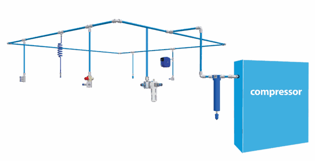
A piping network must be sized to maintain adequate flow and pressure across all outlets, with minimal loss between the compressor and end use. Pressure drop is primarily influenced by pipe diameter, internal surface roughness, system layout, and fittings design.
Before troubleshooting, confirm that a pressure drop actually exists.
What to check:
- Compressor discharge pressure
- Pressure at the receiver
- Pressure at the point of use during normal operation
- Pressure during peak demand
A small pressure difference at idle may be acceptable. A significant drop during production indicates a flow or distribution issue.
Rule of thumb:
A pressure drop of more than 10% between the compressor and point of use warrants investigation.
How to Check Pressure at Key Points in the System
Before drawing conclusions, pressure needs to be measured consistently and under comparable conditions.
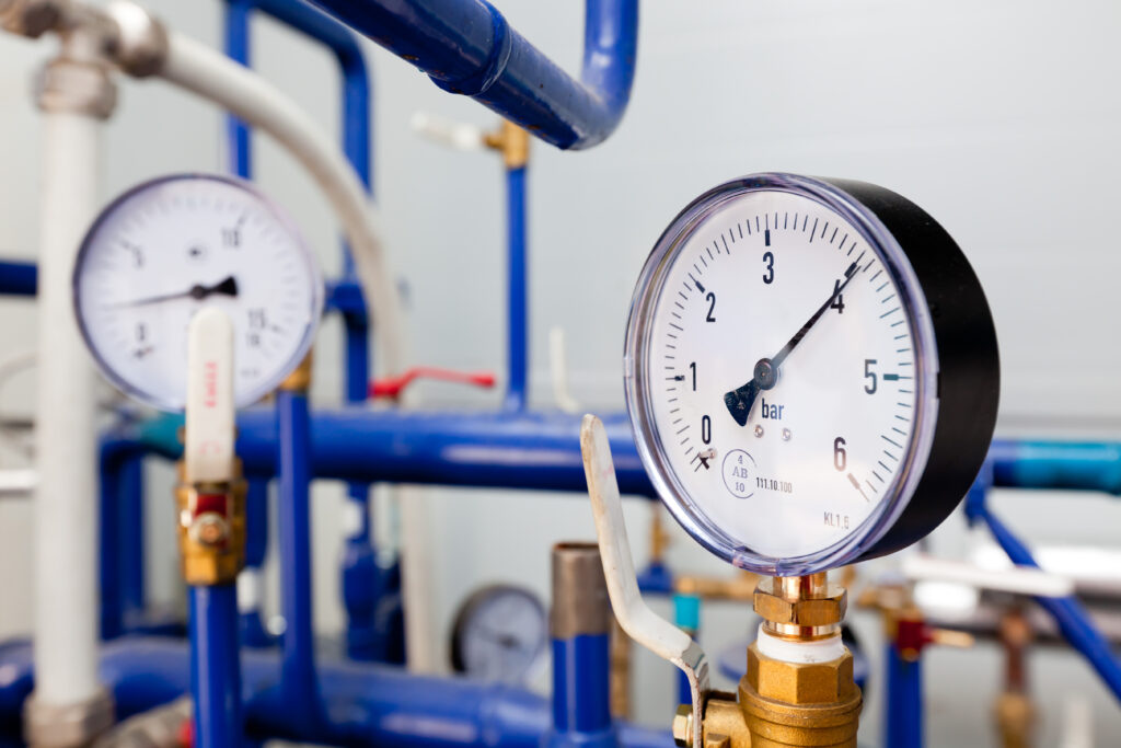
Compressor discharge pressure
This is typically available on the compressor controller or discharge gauge. Record the pressure while the compressor is running under normal load, not during idle or unload cycles.
Pressure at the receiver
Check the gauge on the air receiver or install a temporary test gauge if required. The receiver pressure should closely reflect discharge pressure. A noticeable drop here may indicate restrictions between the compressor and receiver or issues with isolation valves.
Pressure at the point of use during normal operation
Measure pressure at the outlet or drop while equipment is operating under typical conditions. This provides a baseline for day-to-day performance.
Pressure during peak demand
Repeat the measurement when multiple tools or machines are operating simultaneously. Pressure drop often only appears under peak flow conditions, which is why systems can appear acceptable during light use.
Tip:
Record all readings at the same time interval and compare the differences. The size and location of the pressure drop usually point directly to the problem area.
Incorrect pipe sizing is one of the most common contributors to pressure drop. For a breakdown of where sizing decisions typically fail, see Common Pipe Sizing Mistakes in Compressed Air Systems.
Step 2: Check Demand vs System Capacity
Pressure drop is often caused by a small number of high-resistance components rather than the entire system.
Common culprits:
- Undersized valves or regulators
- Quick couplings with restrictive internal bores
- Blocked or contaminated filters
- Flexible hose lengths that are too long or too small in diameter
Measure pressure before and after suspected components to isolate where the loss occurs.
Step 3: Inspect the Pipe Network Layout
Even correctly sized pipework can suffer pressure loss if the layout restricts airflow.
Look for:
- Long pipe runs with no looping
- Excessive elbows, tees, or tight directional changes
- Dead ends that trap air
- Drops taken from the bottom of the main line
Best practice:
Looped systems, smooth flow paths, and correctly positioned drops all reduce friction losses and improve pressure stability.

If pipe diameter is suspected, use our Compressed Air Pipe Sizing Chart to compare existing pipework against actual airflow demand and system length.
Why Pipe Layout Has Such a Big Impact on Pressure Drop
Pipe sizing is only part of the equation. Layout directly affects airflow resistance.
Long pipe runs with no looping
Straight, single-direction runs force all airflow through one path. As demand increases, velocity rises and friction losses increase. Looped systems distribute airflow from multiple directions, reducing velocity and stabilising pressure.
Excessive elbows, tees, or tight directional changes
Each change in direction creates turbulence. Turbulence increases friction losses and disrupts smooth airflow, particularly at higher velocities. Multiple fittings can create more pressure drop than several metres of straight pipe.
Dead ends that trap air
Dead ends contribute no useful airflow but still increase system volume and turbulence. They can also accumulate condensate and debris, further restricting flow over time.
Drops taken from the bottom of the main line
Taking drops from the bottom of the pipe encourages condensate and contaminants to enter the branch line. This increases restriction at regulators, filters, and tools, contributing to localised pressure loss.
Read our guide: Design Considerations for Compressed Air Piping Systems
Step 4: Identify Localised Restrictions
Pressure drop is often caused by a small number of high-resistance components rather than the entire system.
Common culprits:
- Undersized valves or regulators
- Quick couplings with restrictive internal bores
- Blocked or contaminated filters
- Flexible hose lengths that are too long or too small in diameter
Measure pressure before and after suspected components to isolate where the loss occurs.
Step 5: Check for Leaks (Under Load)
Air leaks contribute directly to pressure loss, particularly during peak demand.
Key mistake:
Checking for leaks only when the system is idle.
Leaks that seem minor at rest can become significant when system pressure fluctuates under load. Ultrasonic testing or staged isolation can help identify problem areas.

How to Conduct a Staged Isolation Leak Check
Checking for leaks only when the system is idle often understates the real issue. A staged isolation test helps identify where leaks are occurring and how significant they are.
Step 1: Establish a baseline
With the system pressurised and all downstream valves open, record compressor load/unload behaviour or pressure decay over a fixed time period during production.
Step 2: Isolate sections progressively
Close isolation valves feeding specific zones, branches, or production areas one at a time. Allow the system to stabilise after each isolation and observe changes in pressure stability or compressor cycling.
Step 3: Compare results
A noticeable improvement after isolating a section indicates leaks or excessive demand within that zone. Repeat the process to narrow down the exact area.
Step 4: Investigate under load
Once a problem zone is identified, inspect fittings, hoses, regulators, and connections while equipment is operating. Ultrasonic leak detectors are particularly effective in noisy environments.
Key point:
Leaks that appear insignificant at rest can represent a major airflow loss when pressure fluctuates during peak demand.
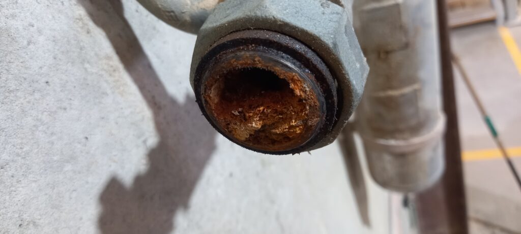
Step 6: Review Pipe Condition and Internal Surface
Older systems or poorly selected materials may suffer from internal corrosion, scaling, or contamination.
Symptoms include:
- Gradual increase in pressure drop over time
- Debris in filters or tools
- Inconsistent pressure despite stable demand
Smooth internal bore pipework significantly reduces friction losses and supports consistent airflow.
Live System Checks
In an operating facility, internal pipe condition can be assessed without shutting the system down.
What to check during normal operation:
-
Inspect filters, drains, and regulators for rust particles, scale, oil residue, or debris. Contamination here often reflects what is happening upstream inside the pipe.
-
Check automatic drains and condensate traps. Excessive solids or discoloured condensate can indicate internal corrosion or material breakdown.
-
Review maintenance records for increasing filter change frequency or repeated regulator failures, which often point to deteriorating internal surfaces.
Targeted pressure comparisons:
Measure pressure across specific sections of the network, particularly older pipe runs. A growing pressure difference over time, without increased demand, is a strong indicator of internal restriction.
Spot inspections during planned maintenance:
Where possible, remove a fitting, valve, or unused drop cap during scheduled downtime. Even a small visual inspection can reveal internal roughness, corrosion, or build-up that contributes to friction losses.
Why internal surface matters:
As internal surfaces degrade, friction increases and effective pipe diameter reduces. This raises air velocity and pressure drop, even if the original pipe sizing was adequate.
Best practice:
Pipework with a smooth internal bore maintains consistent airflow, minimises turbulence, and supports stable pressure over the life of the system.
Step 7: Avoid the “Turn Up the Pressure” Trap
Increasing compressor pressure is often used as a quick fix. While it may restore tool performance temporarily, it increases energy consumption and accelerates equipment wear.
Bandaid solution:
Every unnecessary increase in pressure raises operating costs without solving the underlying issue.
The correct solution almost always sits in the air distribution network, not the compressor setpoint.
A Structured Troubleshooting Approach
Pressure drop is rarely caused by a single issue. It is usually the combined effect of layout decisions, component selection, and system growth over time.
These checks don’t require specialist equipment or complex calculations, but they do require a methodical approach. Done properly, they often reveal simple fixes with immediate performance and efficiency gains.
Effective pressure drop troubleshooting follows a simple sequence:
-
- Measure pressure at key points
- Compare demand to system capacity
- Inspect layout and fittings
- Isolate restrictions and leaks
- Review pipe sizing and condition
Skipping steps runs the risk of incorrect fixes and recurring issues.
Final Takeaway
Pressure drop is not inevitable. It is usually the result of specific, correctable system issues.
A structured troubleshooting process, combined with correct pipe sizing and thoughtful system design, delivers immediate performance improvements and long-term efficiency gains.
When to Get Expert Support
Pressure drop problems can be interconnected. Pipe sizing, layout, fittings, and future expansion all influence performance.
Infinity Pipe Systems works with facilities to assess compressed air networks, identify pressure drop causes, and design distribution systems that deliver stable pressure and efficient flow over the long term. Get in touch with our team to discuss your projects needs.

Pressure Drop Troubleshooting Checklist
Use this checklist to methodically identify the cause of pressure drop before making changes to compressor settings or adding capacity.
Download the pdf version of this checklist here Pressure Drop Troubleshooting checklist.
Measure First
☐ Confirm compressor discharge pressure under normal load
☐ Record receiver pressure during operation
☐ Measure pressure at the point of use
☐ Repeat measurements during peak demand
Compare Demand to Capacity
☐ Confirm actual airflow demand matches system design assumptions
☐ Identify pressure changes when multiple drops operate simultaneously
☐ Review whether system growth has occurred since installation
Inspect Layout and Distribution
☐ Check for long, single-direction pipe runs without looping
☐ Identify excessive elbows, tees, or tight directional changes
☐ Remove or isolate dead ends where possible
☐ Confirm drops are taken correctly from the main line
Identify Local Restrictions
☐ Measure pressure before and after regulators, filters, and valves
☐ Review quick couplings and hoses for restrictive internal bores
☐ Check filters for contamination or blockage
Check for Leaks Under Load
☐ Conduct staged isolation during normal production
☐ Observe compressor cycling and pressure stability after isolations
☐ Investigate suspect zones while equipment is operating
Review Pipe Condition
☐ Inspect filters, drains, and traps for corrosion or debris
☐ Compare pressure across older pipe sections
☐ Review maintenance trends for increasing restrictions over time
Avoid Short-Term Fixes
☐ Do not increase compressor pressure until distribution issues are confirmed
☐ Prioritise correcting pipe sizing, layout, and restrictions
☐ Document findings to support long-term system improvements
Need help diagnosing pressure drop in your compressed air system?
Pressure instability, underperforming tools, and rising energy costs are often symptoms of underlying distribution issues, not compressor capacity.
Our Infinity team can assess your compressed air network, pinpoint the source of pressure drop, and recommend practical improvements across pipe sizing, layout, and system condition to restore reliable performance.
Call: 1300 272 982
Email: info@infinitypipesystems.com.au
Or contact us online: https://infinitypipesystems.com.au/contact-us
Solve the cause, not the symptom, and keep your system performing as intended.